
DIY subs for the LS3/5A
This project would have been impossible without the help and support of Jo Ki, Andy Whittle and Ken Kessler. As well as inspiring me to add some subs to my LS3/5As, Jo went way beyond the call of duty and opened up his AB1s in order to check the dimensions I had calculated. Andy is the designer of the original AB1 and following an approach from Ken, very generously agreed to supply details of the AB1’s crossover for inclusion here.
Quite a lot of information about the AB1 was available from reviews and from the Rogers’ literature. The design is a fourth order bandpass subwoofer with -3dB point at 55Hz. The LS3/5A is intended to be fed from the subwoofer through a second order high pass filter which takes a lot of the strain off from the LS3/5A and as well as extending the frequency response downwards also allows a couple of dB extra spl from the combo.
An email to KEF resulted in the data sheet for the B110 arriving next morning in the post (thank you Ron). The B110 I used was the SP1003 which was used in the 15 ohm LS3/5A, but any of the B110 series will work fine in this application and the SP1228 version is usually used.
At the time I didn’t have the internal dimensions of the AB1. Design information for sub woofers including Fourth Order Bandpass systems was available from the Subwoofers DIY page which provides an excellent resource for sub woofer builders. At the time a design spreadsheet written in Excel called”Bandpass” could be downloaded.

“Plugging in” the values for Vas, Fs and Qts from the B110 data sheet and using a value of -3dB at 55Hz into “Bandpass” gave me values for Vf, (the net volume of the vented section of the enclosure) and for Vr (the sealed section). The dimensions I calculated for the internal chambers were confirmed later by Jo Ki who kindly measured his AB1s for me.
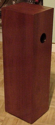
The external dimensions are 570mm high (the original AB1 has a 25mm plinth bringing the height up to 595mm), 190mm wide and 160mm deep. The cabinet walls are made from 18mm MDF and the internal baffle for the B110 drive unit is made from 12mm MDF.
Click on the images for a large version of Jo Ki’s drawings.
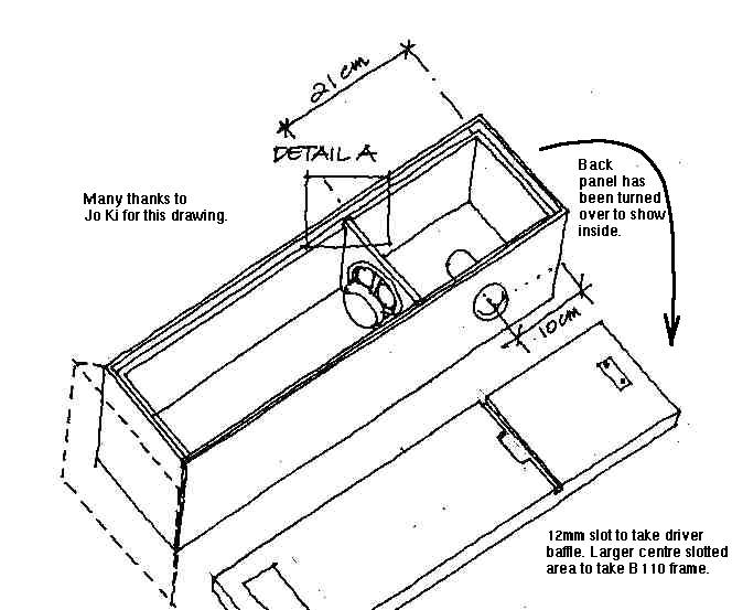
Note that the drive unit chassis is a little too wide to fit in the cabinet. To overcome this the original AB1 has a slot cut in both the front and backpanels. The slot is shown in Jo Ki’s drawing. The rear panel is slotted to accept the 12mm baffle. In order to ensure that the seal between the two compartments is airtight when the back panel is screwed on the rear edge of the 12mm baffle has a rubber strip applied. I used self adhesive foam draft excluder strip.

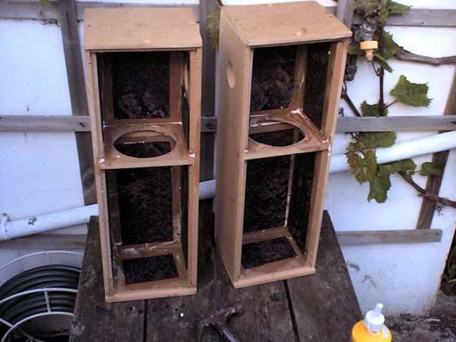
A local timber merchant cut the panels from a single sheet of 4ft x 4ft MDF and the panels (with the exception of the back) were glued and screwed together. All joints were sealed using frame sealant, it is essential that they are airtight.
The AB1’s port is 4.2cm in diameter and 8.5cm long, I hunted round for some plastic tube 4.2cm in diameter before realising that the plastic tube that the frame sealant had come in was 4.6cm inside diameter. Re-calculating the port gave a new length of 10.5cm for this diameter, an excellent result given that the frame sealant tube was exactly 21cm in length!
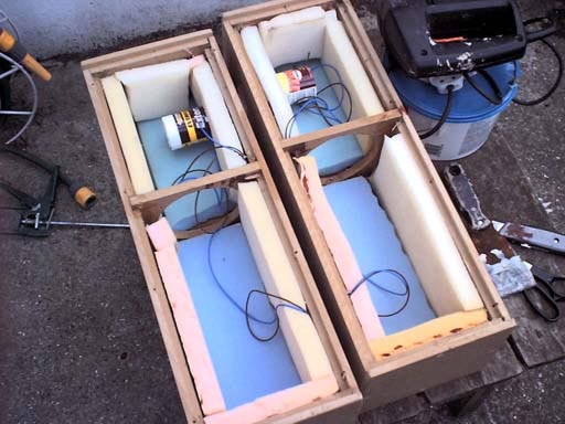
Car body damping pads were applied to all internal cabinet walls and on top of these (12 – 25mm) high density foam was glued. The drive units were mounted onto the baffles using grommet strip to make a good air seal. A loose roll of foam is then placed in the bottom section of each cabinet. It is important that the rear panel makes a good air tight seal and so soft rubber draught excluder strip was used on all the edges. Foam draught excluder strip works well too.
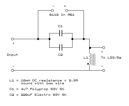
Andy Whittle, the designer of the AB1 kindly supplied the circuit of the AB1 crossover for use here. Thanks both to Andy and to Ken Kessler for their help.
I was unable to obtain 16mH inductors off the shelf so I used 15mm Ferrite Cored inductors obtained from Wilmslow Audio and increased the value of the capacitors to 240uF to keep the crossover turnover frequency the same. Wilmslow Audio also sell B110 drive units, damping pads and suitable non-polarised electrolytic capacitors.

The crossover components were mounted on a simple PCB. Unwanted areas of copper can be removed with a craft knife. Components are mounted on the copper side of the board and the ferrite inductor is secured to the PCB using cable ties through 4 small holes drilled in the board.
Jo Ki feeds his AB1s in parallel with the LS3/5As. Although both speakers are working in the crossover region, in practice this has not proved a problem and Jo’s system sounds superb. Jo does not place his LS3/5As on top of the AB1s. Jo Ki’s Method.